Week 13: Networking and Communications
What should I do this week?
In this thirteenth week of Fab Academy, there are two types of assigments. The individual assigment is to design, build, and connect wired or wireless node(s) with network or bus addresses.
The group assigment is to Send a message between two projects. Further learnings are listed below:
- Understand the workflows used in network design
- Implement and interpret networking protocols and/or communication protocols
- Add an output device to a microcontroller board you've designed and program it to do something.
- Explained the programming process used
- Explain the mistakes that I had made and how I corrected it
- Include hero shots of the board
- Link to the group assignment page
- Include the design files used
- Try out a cool experiments
The following are the softwares that I have used for learning various operations:
- Arduino IDE : Programming
- MIT Mods : Machine Management
The main goal of this weeks assigment is to create a network using our custom PCB boards using a wired or wireless connection. Since I had worked with wireless communication devices like bluetooth module, I plan to go with I2C wired protocol, with main aim to make the project modular. Since the lab is closed due to the pandemic, my main goal is to complete the design and wait for the lab to open to try it out.
Week 13: Action Plan
| |
|
|---|---|
| Wednesday | Prof. Neil's class on Networking and Communication |
| Thursday | Researching about various protocols availabe |
| Friday | Designing master board with I2C communication ports |
| Saturday | Documentation |
| Sunday | Documentation |
| Monday | Documentation |
| Tuesday | Documentation |
What is embedded communication?
Embedded communication is the process of sending information between two MCUs or from one circuit to other. For a communication to happen there needs to be a transmitter and a receiver. Communication may be in one direction or in both directions, there are different classifications according to this, but the basic classification is Synchronous and Asynchronous communication. The different types of communication are listed below:
- Parallel: Parallel interfaces transfer multiple bits at the same time. They usually require buses of data - transmitting across eight, sixteen, or more wires. Data is transferred in huge, crashing waves of 1’s and 0’s.An 8-bit data bus, controlled by a clock, transmitting a byte every clock pulse. For communication 9 wires are required,
- Series: Serial interfaces stream their data, one single bit at a time. These interfaces can operate on as little as one wire, usually never more than four.Example of a serial interface, transmitting one bit every clock pulse. For communication 2 wires are required
- Asynchronous: Asynchronous means that data is transferred without support from an external clock signal. This transmission method is perfect for minimizing the required wires and I/O pins, but it does mean we need to put some extra effort into reliably transferring and receiving data. The serial protocol we’ll be discussing in this tutorial is the most common form of asynchronous transfers. It is so common, in fact, that when most folks say “serial” they’re talking about this protocol
- Synchronous: A synchronous serial interface always pairs its data line(s) with a clock signal, so all devices on a synchronous serial bus share a common clock. This makes for a more straightforward, often faster serial transfer, but it also requires at least one extra wire between communicating devices. Examples of synchronous interfaces include SPI, and I2C.
Communication Protocols
A communication protocol is a system of rules that allow two or more entities of the communications system to transmit information via any kind of variation of a physical quantity. Communications protocols cover authentication, error detection and correction, and signaling. They can also describe the syntax, semantics, and synchronization of analog and digital communications. Communications protocols are implemented in hardware and software. There are thousands of communications protocols that are used everywhere in analog and digital communications. Communications devices have to agree on many physical aspects of the data to be exchanged before successful transmission can take place. Rules defining transmissions are called protocols. There are two main categories in this.
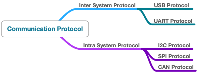
Inter System Protocol
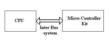
The inter-system protocol using to communicate the two different devices. Like communication between computer to microcontroller kit. The communication is done through an inter bus system. The different categories of intersystem protocol mainly include the following:
- UART Protocol
- USART Protocol
- USB Protocol
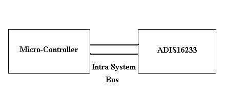
Intra System Protocol
The Intra system protocol is used to communicate the two devices within the circuit board. While using these intra system protocols, without going to intrasystem protocols we will expand the peripherals of the microcontroller. The circuit complexity and power consumption will be increased by using the intrasystem protocol. Using intra system protocols circuit complexity and power consumption, the cost is decreased and it is very secure to accessing the data. The different categories of intrasystem protocol mainly include the following.
- I2C Protocol
- SPI Protocol
What is I2C Protocol
I2C combines the best features of SPI and UARTs. With I2C, you can connect multiple slaves to a single master and you can have multiple masters controlling single, or multiple slaves. This is really useful when you want to have more than one microcontroller logging data to a single memory card or displaying text to a single LCD. I2C is a serial communication protocol, so data is transferred bit by bit along a single wire (the SDA line). I2C only uses two wires to transmit data between devices: SDA (Serial Data) - The line for the master and slave to send and receive data and SCL (Serial Clock) - The line that carries the clock signal.
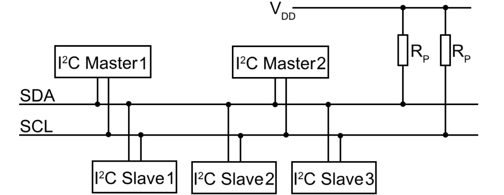
I2C is a serial communication protocol, so data is transferred bit by bit along a single wire (the SDA line).I2C is synchronous, so the output of bits is synchronized to the sampling of bits by a clock signal shared between the master and the slave. The clock signal is always controlled by the master.
With I2C, data is transferred in messages. Messages are broken up into frames of data. Each message has an address frame that contains the binary address of the slave, and one or more data frames that contain the data being transmitted. The message also includes start and stop conditions, read/write bits, and ACK/NACK bits between each data frame.
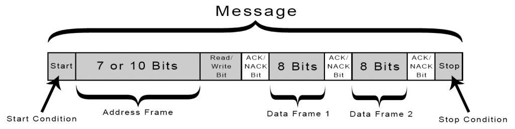
- Start Condition: The SDA line switches from a high voltage level to a low voltage level before the SCL line switches from high to low.
- Stop Condition: The SDA line switches from a low voltage level to a high voltage level after the SCL line switches from low to high.
- Address Frame: A 7 or 10 bit sequence unique to each slave that identifies the slave when the master wants to talk to it.
SPI Protocol
SPI is a common communication protocol used by many different devices. For example, SD card modules, RFID card reader modules, and 2.4 GHz wireless transmitter/receivers all use SPI to communicate with microcontrollers.One unique benefit of SPI is the fact that data can be transferred without interruption. Any number of bits can be sent or received in a continuous stream. With I2C and UART, data is sent in packets, limited to a specific number of bits. Devices communicating via SPI are in a master-slave relationship. The master is the controlling device (usually a microcontroller), while the slave (usually a sensor, display, or memory chip) takes instruction from the master. The simplest configuration of SPI is a single master, single slave system, but one master can control more than one slave. From now onwards instead of calling Master Slave, I think we should shift to Master and Student.
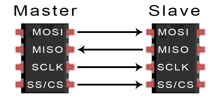
SPI can be set up to operate with a single master and a single student, and it can be set up with multiple students controlled by a single master. There are two ways to connect multiple students to the master.
USB Communication Protocol
USB stands for universal serial bus. Again it is a serial communication of two wire protocol. The data cable signal lines are labeled D+ and D-.This protocol is used to communicate with the system peripherals.USB protocol is used to send and receive the data serially to the host and peripheral devices.USB communication requires a driver software which is based on the functionality of the system.USB device can transfer data on the bus without any request on the host computer. Now a day’s most of the devices are using this technique for communicating with USB protocol. Like computer to communicate with ARM controller using USB. USB transfer the data different modes .first one is slow speed mode 10kbps to 100 kbps; second one is full speed mode 500kbps to 10mbps, high speed mode 25mbps to 400 mbps
Desigining the Board for I2C Communication
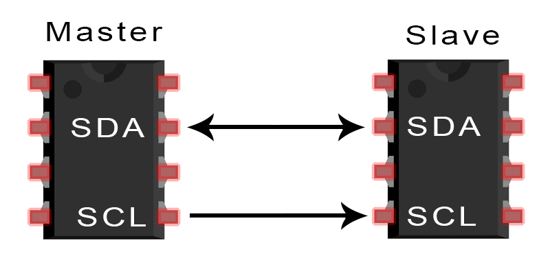
The below image depitcs a simple diagram that shows how the master and the student should be connected to perform the I2C communication. The master sents a signal to the apprpriate terminal in student to execute a action.
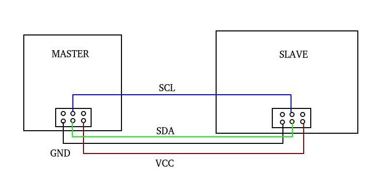
For this week, I had decided to use the board from input/output week as one of student and echo hello world board from Week 6 as the teacher. To make the communication happen, I need to create a custom pullup board from scratch. The pullup board is a simple circuit where, the I2C pins MOSI and SCK are connected to VCC via a resistor.
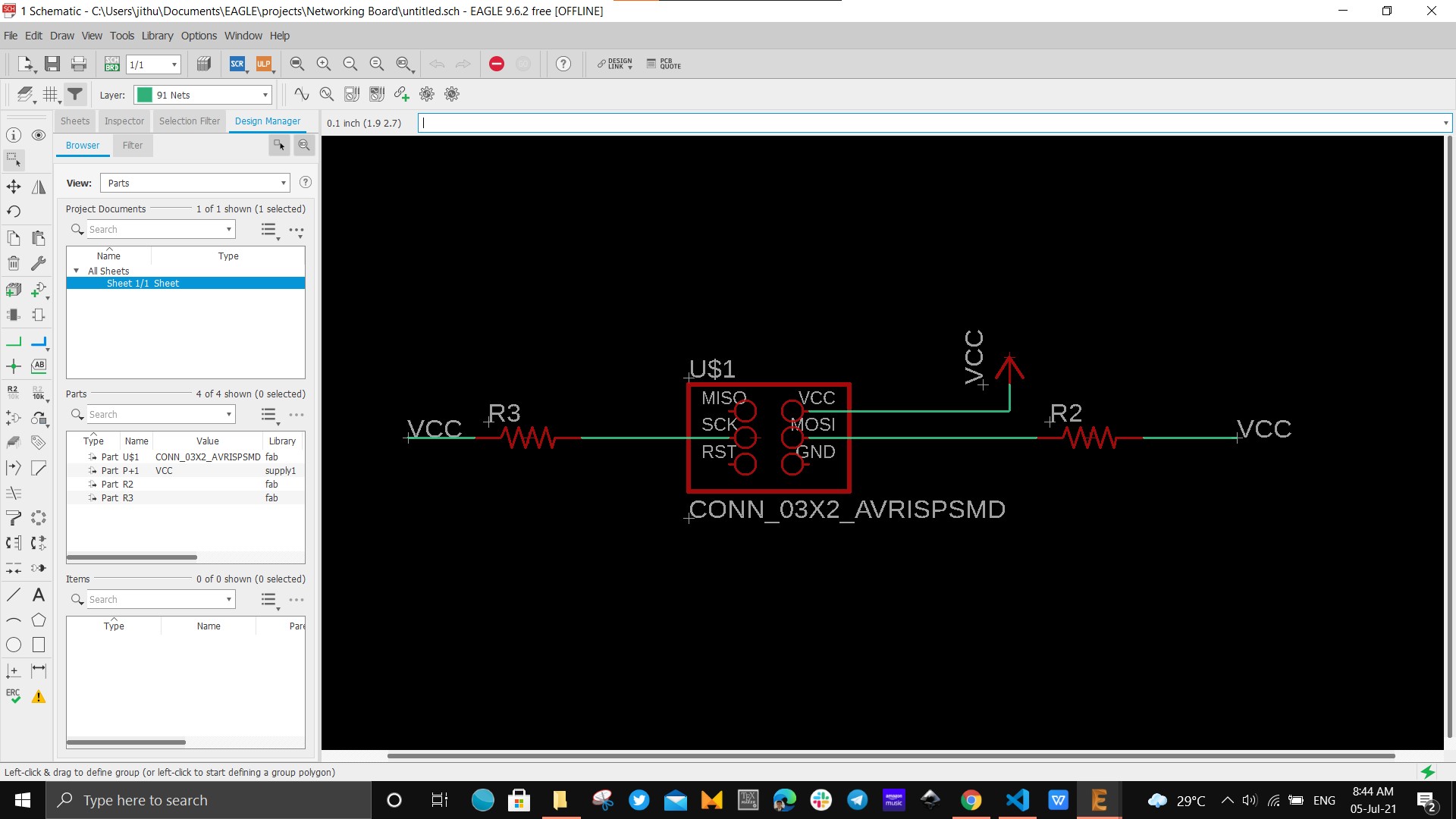
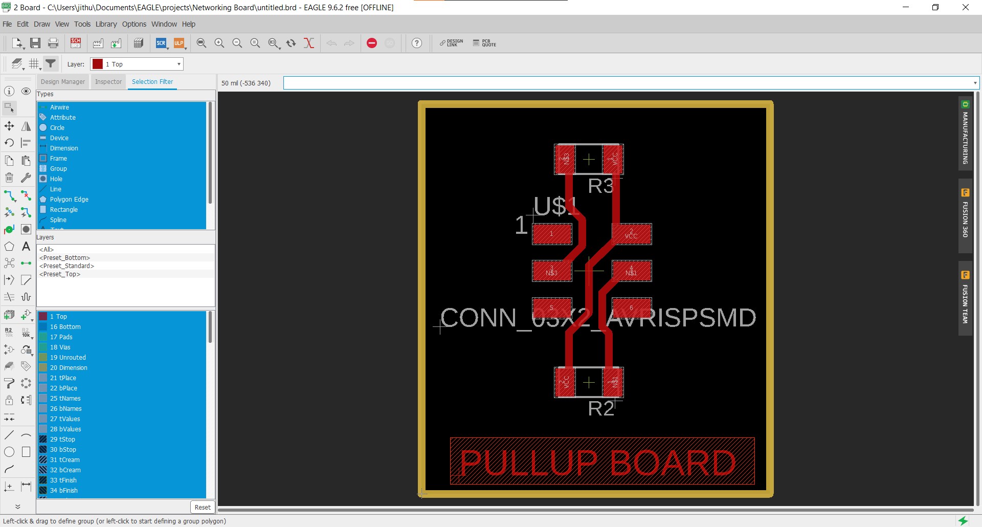
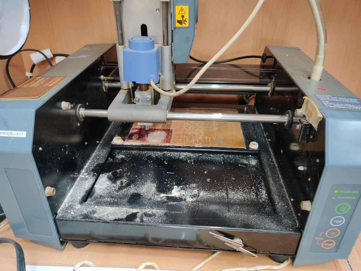
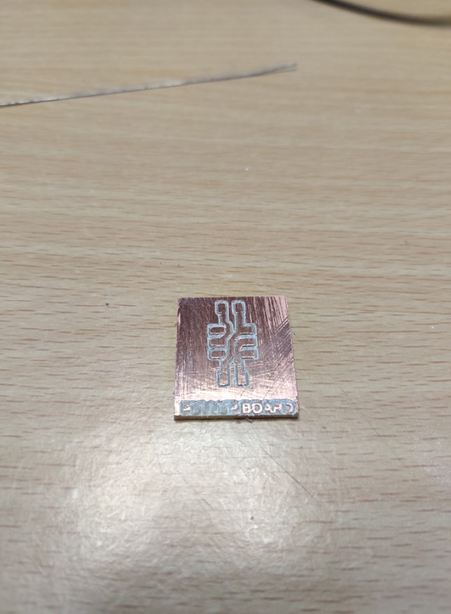
The following image shows the traces for milling the cutting the board. Now U need to millout the PCB using Modella MDX20 PCB Milling machine. I used the same steps that i followed on my previous elecronics design weeks.
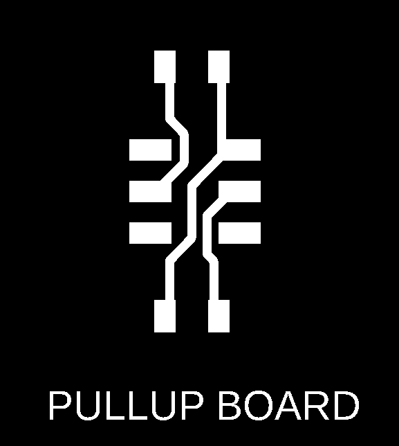

The next step is the milling and cutting process which is conducted using Modela MDX20 PCB Milling Machine. The step used is same as previous weeks. The process went out to be smooth for me and I got the pull up board as expected.
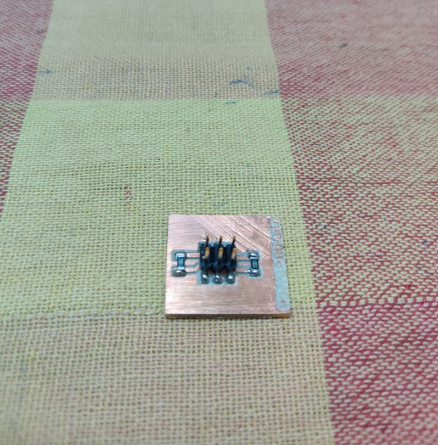
The next step is to solder the components on to the PCB board and it was quite easy. The follwing components were used for pull up board
- 10L Ohm Resistor -2
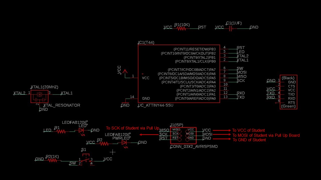
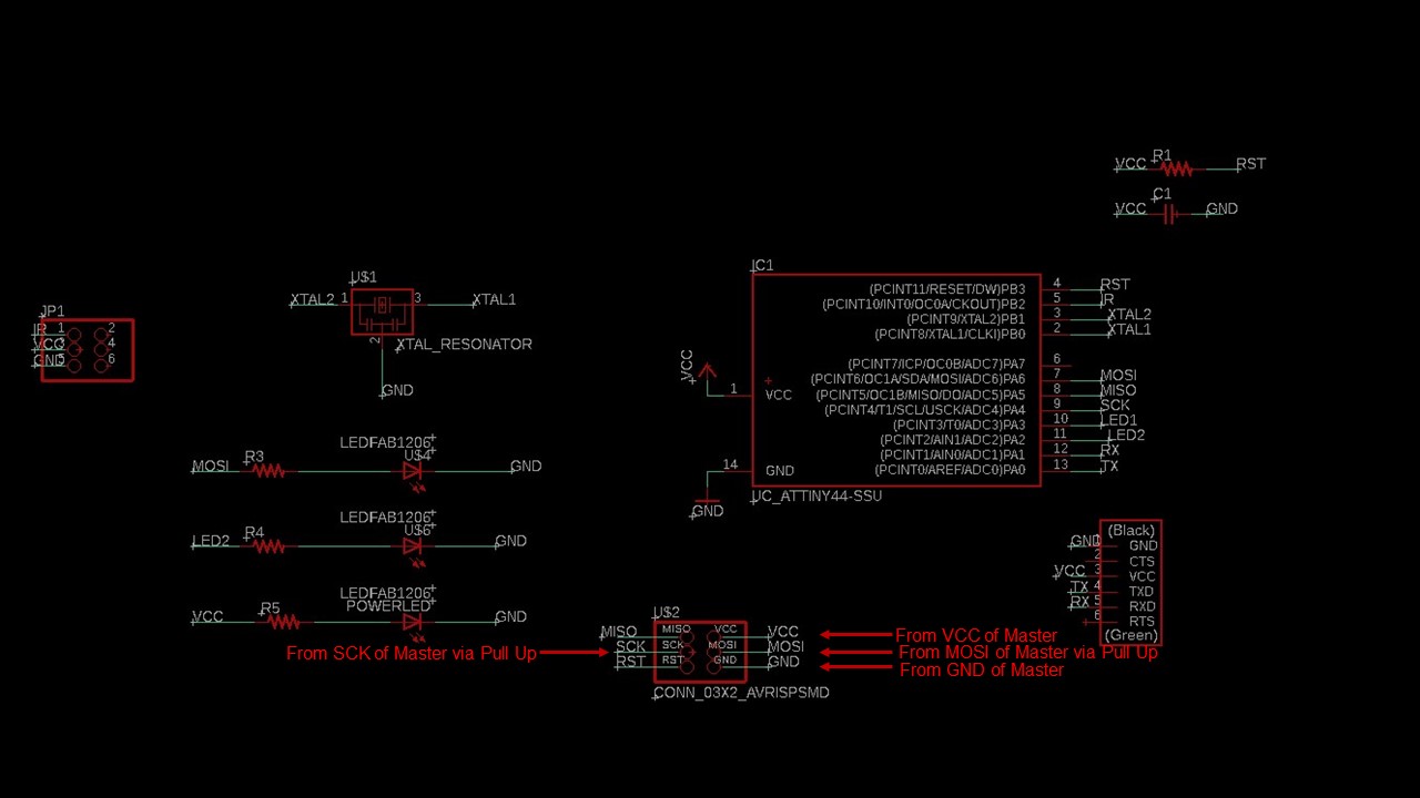
As I had said earlier, I had used Echo Hello World board as the master/teacher board and the input/output week board as the student. The next section will provide the details about the programming using Arduino IDE. The below figure shows the schematic and pins used for communication of Echo Hello World board.
Programming and Testing
The idea of this assignment is to check the wired communication between teacher and the student using I2C. When the button in the teacher board is pressed the LED in the student must light up. For this assigment a seperate library is required called as TinyWire.h for Arduino.
The next step is to write the code for the teacher/master board to actuate LED on the student when a button in pressed using I2C communication. The following is the code for the same.
Master Board
        #include <.TinyWire.h> //Please remove the full stop preceeding the TinyWire.h when used in code
            #define BTN PA7 // Button connected to Digital Pin 3
            byte slave_1 = 10; //Student address

            void setup() {

            pinMode( BTN, INPUT_PULLUP); // intializing Button
            TinyWire.begin(); // intializing Communication
            }

            void loop() {

            if(digitalRead(BTN)==LOW) //If button is pressed
            {
            digitalWrite(LED,HIGH); // led turns on
            TinyWire.beginTransmission(slave_1); // begin transmission to student board
            TinyWire.send('1'); // Sending a message
            TinyWire.endTransmission(); // ending the transmission


            }
            else
            {
            digitalWrite(LED,LOW); // if button is released
            TinyWire.beginTransmission(slave_1);// begin transmission to student board
            TinyWire.send('0');// Sending a message
            TinyWire.endTransmission();// ending the transmission
            }

            }
Student Board
        #include <.TinyWire.h> //Please remove the full stop preceeding the TinyWire.h
            #define LED1 PA6 //led 1 connected to 7
            #define LED2 PA2 //led 2 connected to 8
            byte slave_1 = 10; // slave address

            void setup() {

            TinyWire.begin(slave_1);
            pinMode(LED1, OUTPUT); //initializing led1
            pinMode(LED2, OUTPUT); //initializing led2
            }

            void loop() {
             byte data; // delacring data
            if (TinyWire.available()) // check whether master is available
             data = TinyWire.receive(); // storing recieved data
            if (data == ('1')){ //if recieved data is "1"
            digitalWrite(LED1, HIGH); // led 1 on
            digitalWrite(LED2, HIGH); // led 2 on
            delay(500); //halt for 500 milliseconds
            digitalWrite(LED1, LOW); // led 1 off
            digitalWrite(LED2, LOW); // led 2 off
            delay(500);//halt for 500 milliseconds
            }
            else if (data == ('0')){ //if recieved data is "0"
            digitalWrite(LED1, LOW); // led 1 off
            digitalWrite(LED2, LOW); // led 2 off
            }
            }
Connection and Testing
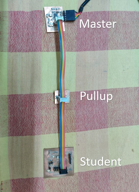
I had connected the extended 6*2 pin header to master and student nodes. The master will be powered using the FTDI connector. The assigment was successful and the video of testing is given below.
Group Assignment
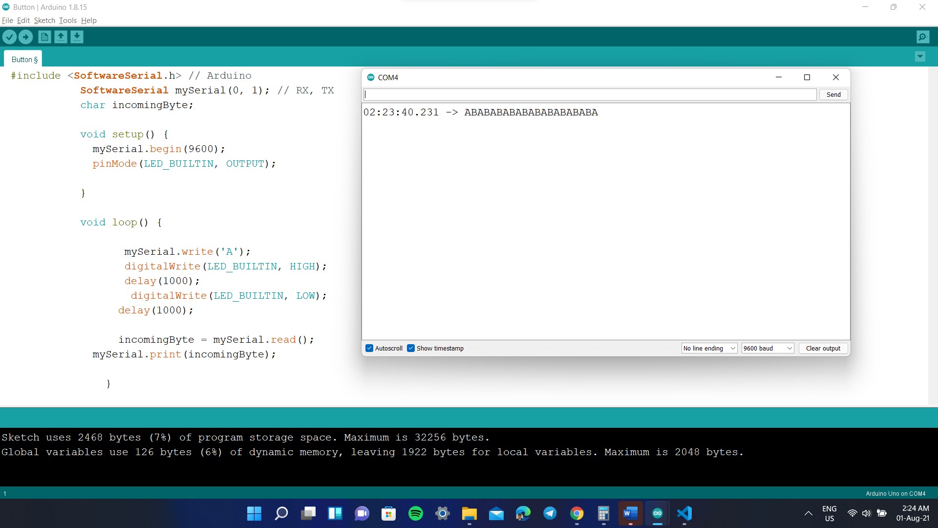
For this group assignment, I had to show the communications between two projects. For that I had selected Arduino as one board and my custom made board used for input week as the secondary board. I had connected the TX/RX pins of Arduino to RX/TX pins of MCU respectively and VCC/GND was also provided from Arduino. The project here is to send data between Arduino and MCU and monitor it using serial monitor. Here the Arduino sends 'A' to the MCU with an LED blink where as MCU checks whether the received message is 'A' and replies with letter 'B' along with an LED blink. The experiment was successful and I will provide the code and video below
Arduino Code
        #include < SoftwareSerial.h> // Arduino
            SoftwareSerial mySerial(0, 1); // RX, TX
            char incomingByte;

            void setup() {
              mySerial.begin(9600);
              pinMode(LED_BUILTIN, OUTPUT);

            }

            void loop() {

                   mySerial.write('A'); //Send the letter
                   digitalWrite(LED_BUILTIN, HIGH);
                   delay(1000);
                    digitalWrite(LED_BUILTIN, LOW);
                  delay(1000);

                  incomingByte = mySerial.read();
              mySerial.print(incomingByte); //Recieve the letter

                }
MCU Code
        #include < SoftwareSerial.h> //Slave
            SoftwareSerial mySerial(0, 1); // RX, TX
            const char node = 'A';
            char incomingByte;

            void setup() {
              mySerial.begin(9600);
              pinMode(PA2, OUTPUT);
            }

            void loop() {

                incomingByte = mySerial.read();
                if (incomingByte == node) { //Check whether letter is A
                  digitalWrite(PA2, HIGH);
                 delay(1000);
                  digitalWrite(PA2, LOW);
                   mySerial.write('B'); //Send B

                }
              }